inglés
 ruso
ruso español
 italiano
 árabe
árabe coreano
 alemán
 Japonés japonés
 vietnamita
 turco
turco
-
-
Caja de cambios de 90 grados de ángulo recto
- Aatmas: sistema de dirección de precisión de la serie
- Sistema de dirección de precisión de la serie aatas
- Precisión de la serie aawas reducde 90 grados
- Tren de dirección estándar de la serie PT-A
- PAW-A serie precisa reducde 90 grados
- En el tren de dirección de entrada del eje de la serie
- Entrada de brida de la serie AT-F reduc90 grados
- Elevador de tornillo sincrónico de la serie RB
- CCW Classic Planetary input to steering (en inglés)
- CCT Classic dirección de entrada del eje
-
Micro reductor de engranreductor
-
-
Panes y panes mecánicos mecánicos
-
Componentes mecánicos mecánicos
- Volante de volante
- La mano
- Varios tipos de las manos
- Colgante Wal Pin/ bispin
- mananti
- Categoría de protección para amortigude choque
- Abrazaderas neumáticas/abrazaderas rápidas
- Piezas de posicionamiento/piezas de guía
- Colocación de perno/buje de posicionamiento
- Pequeñas partes/imán
- Montaje de soportes/Bases/soportes
- Bloque de conexión
- Accesorios de neumáticos
- Pies a nivel de las piernas
- Los castillos de la puerta
- Mango de la mano
- bisagr


-
Motores motores motores motores motores
- Motor de bucle abierto + motor de bucle cerrado + motor de paso de tornillo
- Conductor del motor paso a paso (abierto/cerrado)
- Servomotor de ca + servoconductor de ca
- Servomotor de corriente continua + servoconductor de corriente continua (tipo de pulso + bus)
- DC brushless motor y DC brushless driver
- Motor DD de accionamiento directo + motor lineal
- Controlador/controlador de movimiento programable PLC (tarjeta/máquina de control de visión todo en uno)
- Motor especial a prueba de explosión
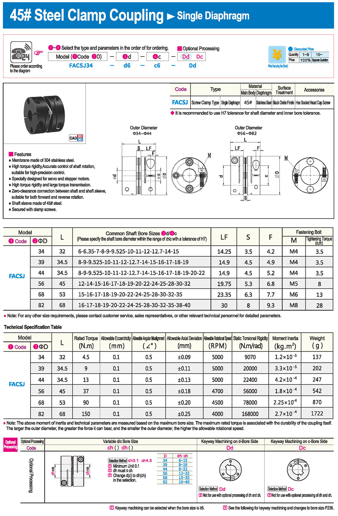
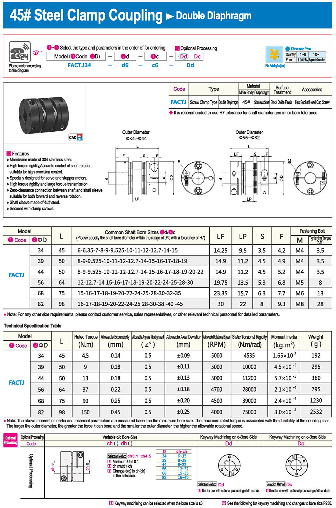
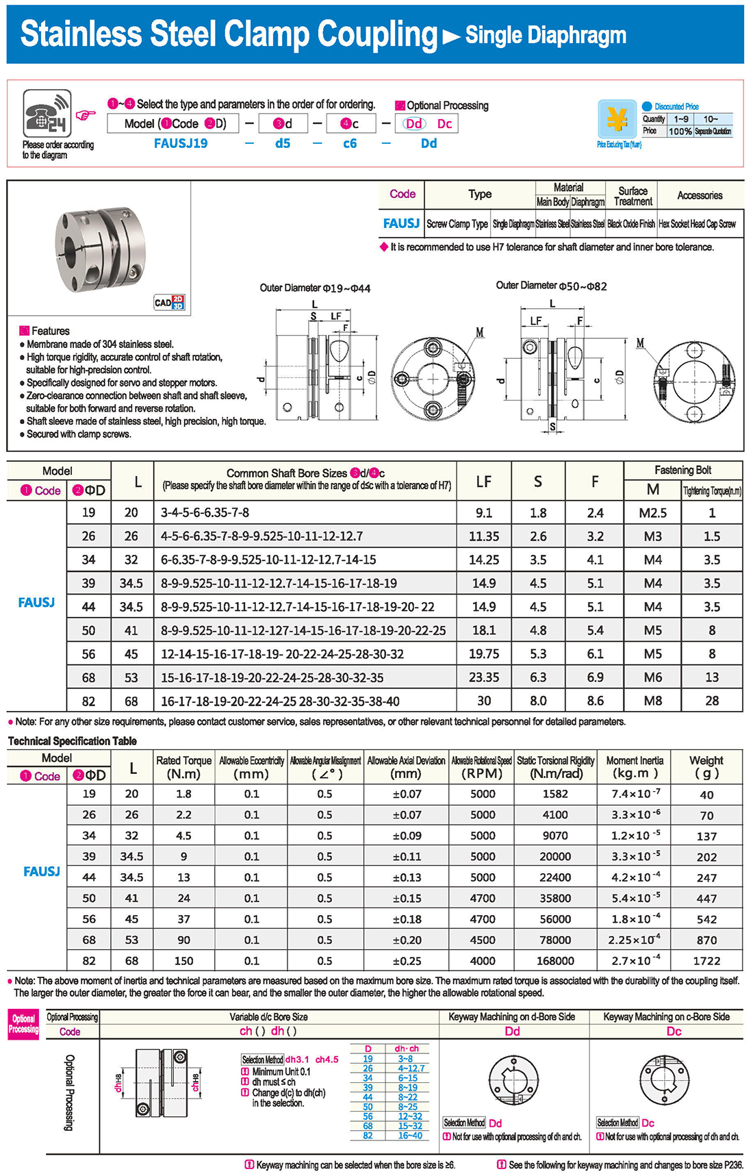
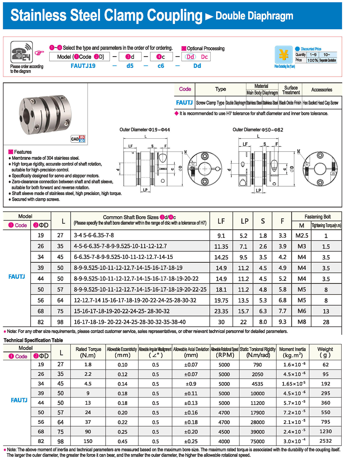
 introducción
 Tabla de especificaciones
 descargar