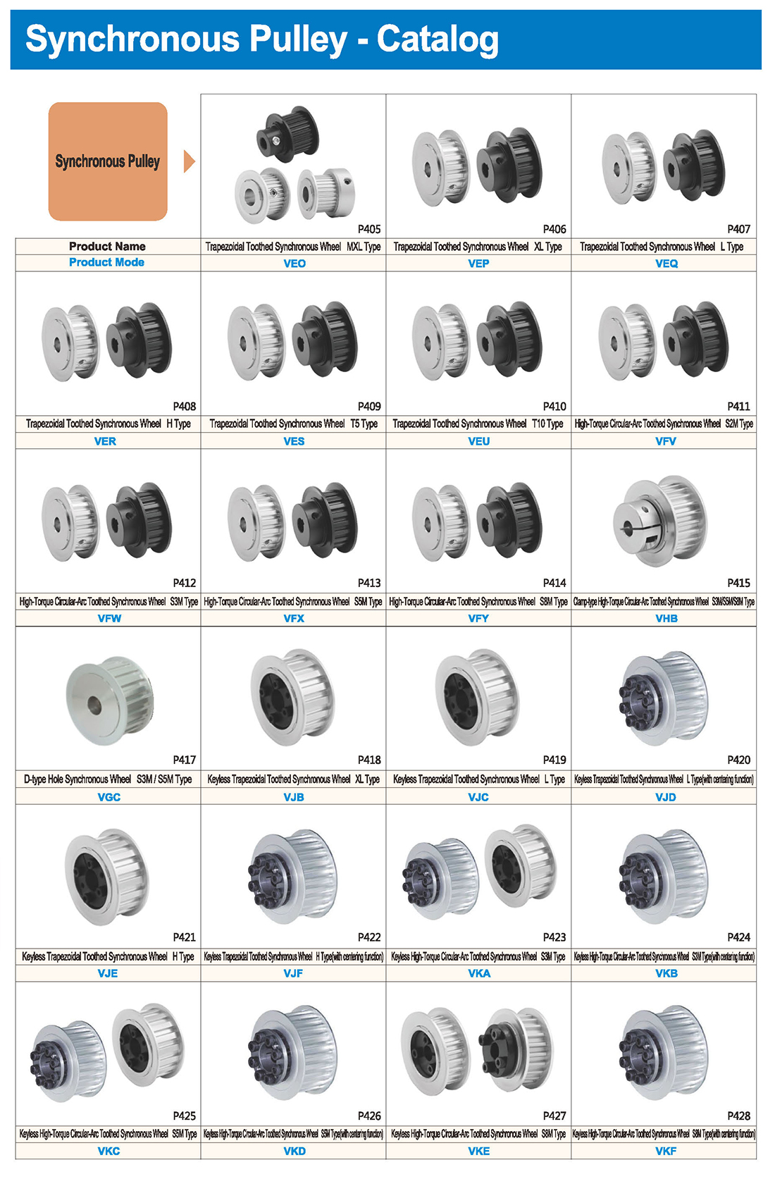
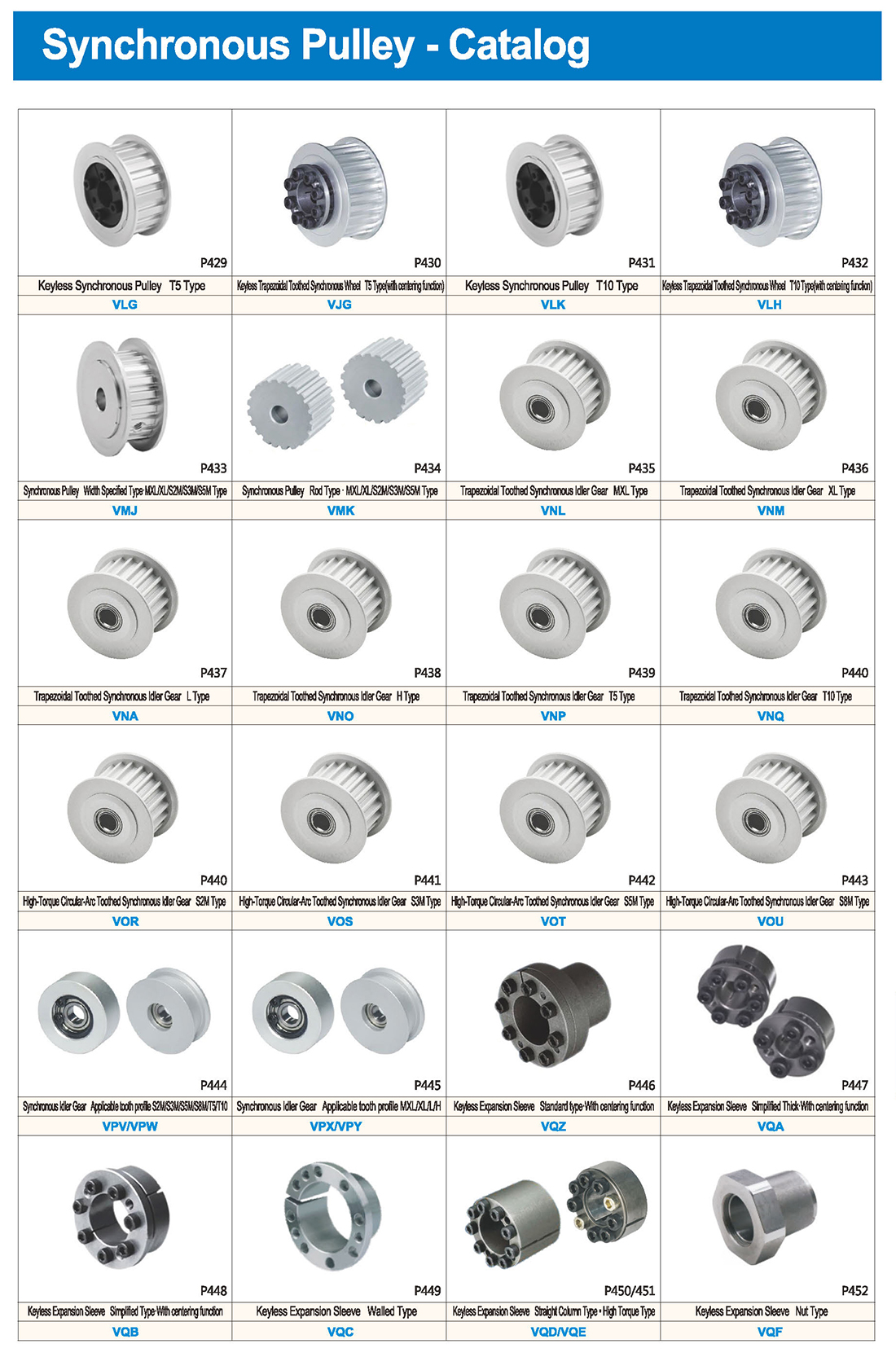
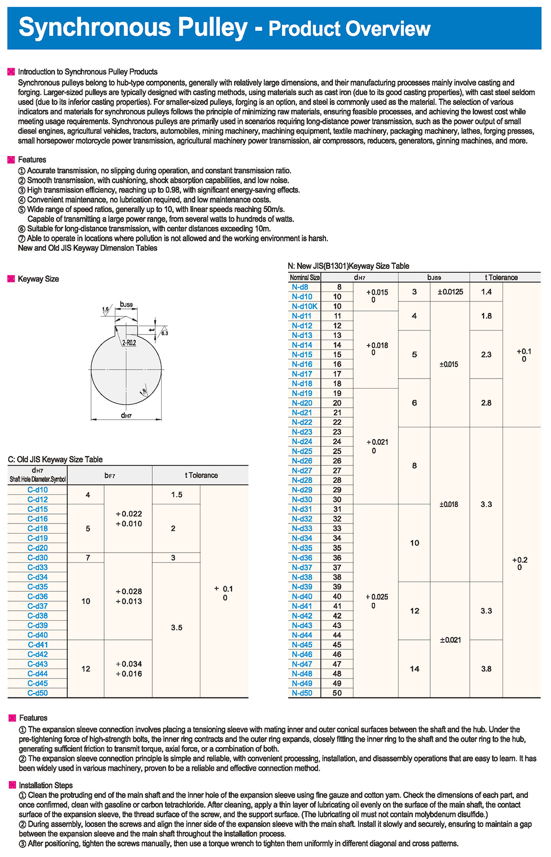
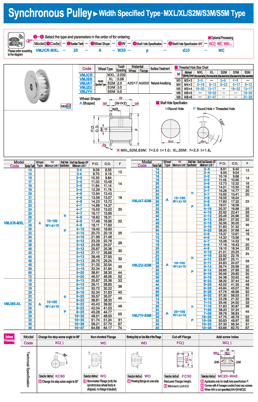
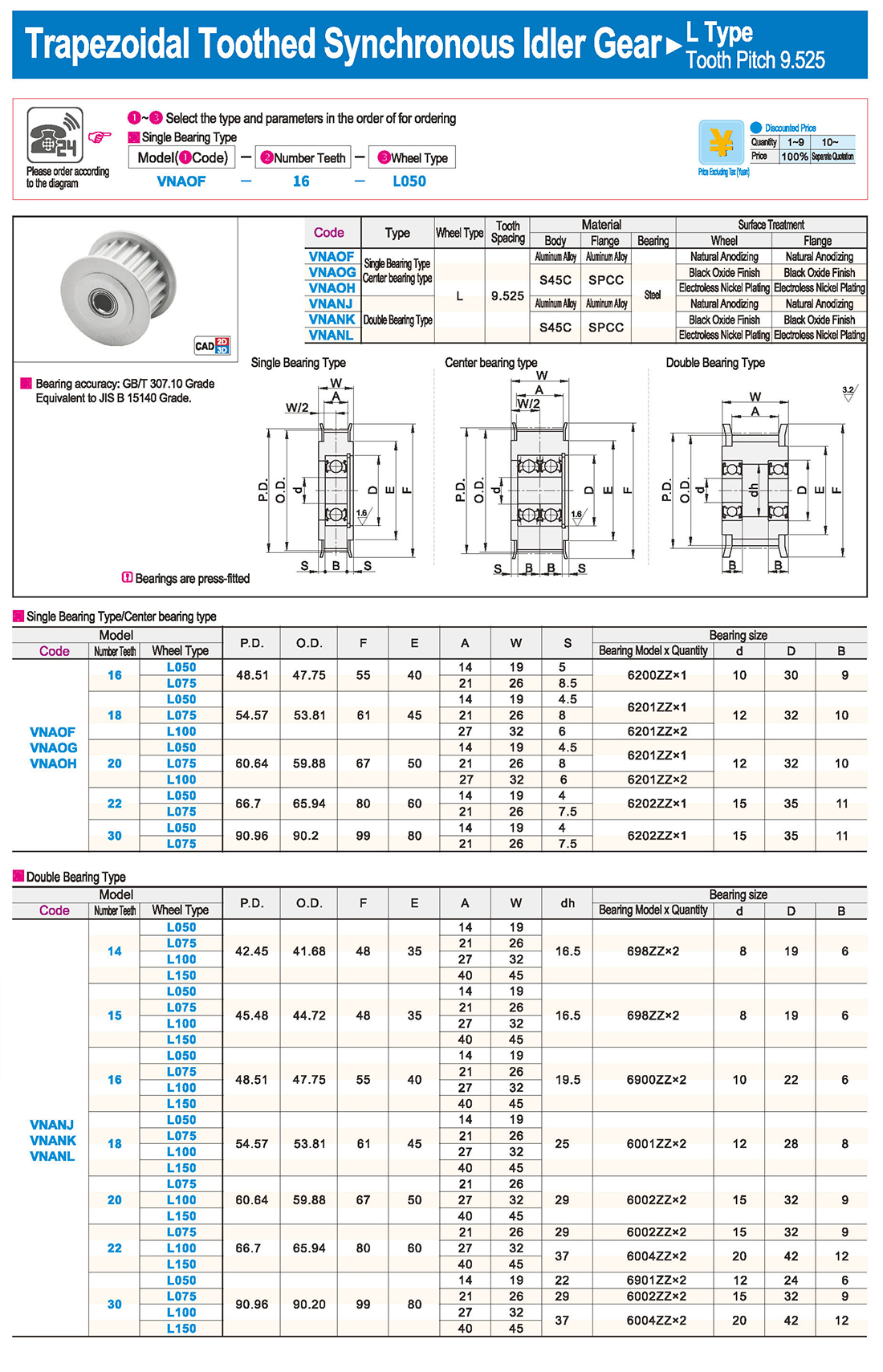
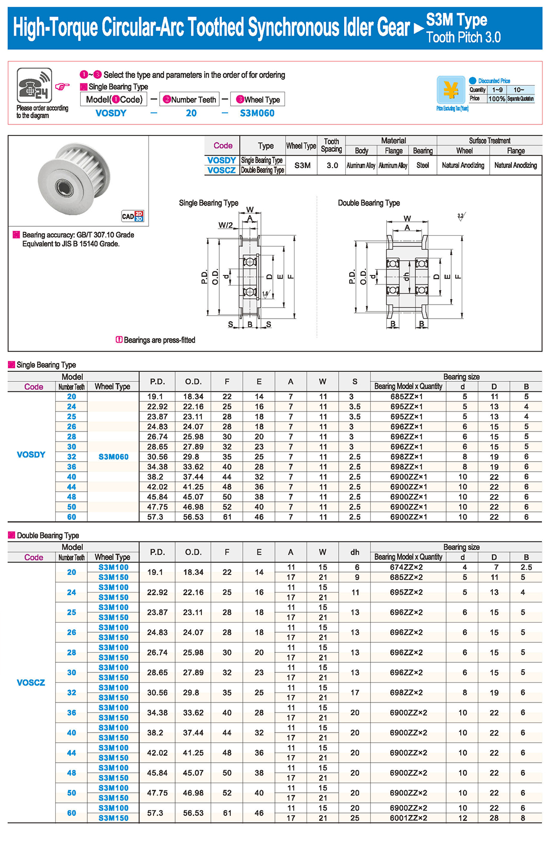
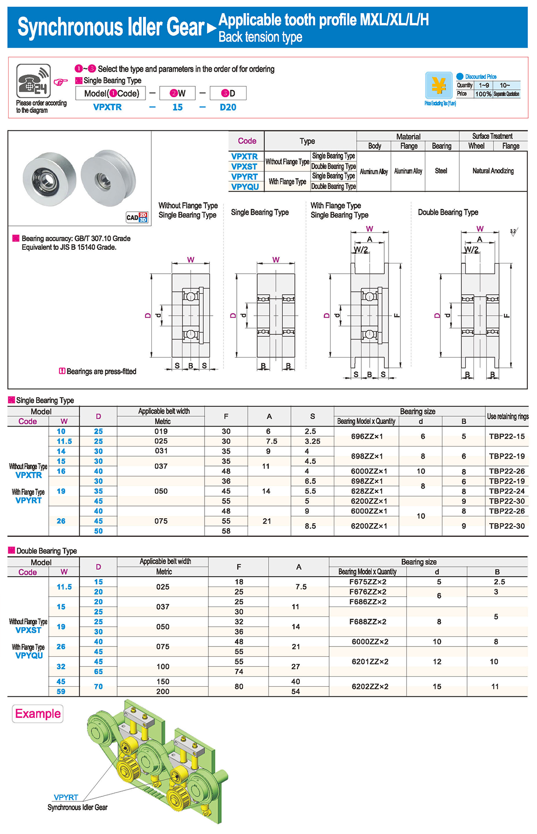
Introducción a los productos de poleas síncronas
Las poleas síncronas pertenecen a componentes de tipo hub, generalmente con dimensiones relativamente grandes, y sus procesos de fabricación involucran principalmente fundición y forja. Las poleas de mayor tamaño son típicamente diseñadas con métodos de fundición, usando materiales como el hierro fundido (debido a sus buenas propiedades de fundición), con acero fundido raramente usado (debido a sus propiedades de fundición inferiores). Para poleas de menor tamaño, la forja es una opción, y el acero se utiliza comúnmente como material. La selección de varios indicadores y materiales para poleas síncronas sigue el principio de minimizar las materias primas, asegurar procesos factibles y lograr el menor costo al mismo tiempo que se cumplen los requisitos de uso. Las poleas sincrónicas se utilizan principalmente en los escenarios que requieren la transmisión de energía de larga distancia, tales como la salida de energía de pequeños motores diesel, vehículos agrícolas, tractores, automóviles, maquinaria minera, equipos de mecani, maquinaria textil, maquinaria de embalaje, tornos, prende forja, pequeña potencia de transmisión de potencia de motocicleta, transmisión de potencia de maquinaria agrícola, compresores de aire, reductores, generadores, desdesmotadores, y más.
características
Transmisión precisa, sin deslizdurante el funcionamiento y una relación de transmisión constante.
Transmisión suave, con amortigu, capacidad de absorción de choque y bajo ruido.
− alta eficiencia de transmisión, alcanzando hasta 0,98, con importantes efectos de ahorro de energía.
④ mantenimiento conveniente, sin necesidad de lubricy bajos costes de mantenimiento.
Rango amplio de velocidades, generalmente hasta 10, con velocidades lineales que alcanzan los 50m/s. Capaz de transmitir un gran rango de potencia, desde varios vatihasta cientos de vati.
Apto para transmisión de larga distancia, con distancias de centro superiores a 10m.
Pueden operar en lugares donde no se permite la contaminación y el entorno de trabajo es duro.
New and Old JIS Keyway Dimension Tables (en inglés)
Los rodde de leva pueden soportar grandes cargas radiales y axiales, así como cargas de impacto y vibración, adecuados para una variedad de entornos de trabajo difíciles.
Features
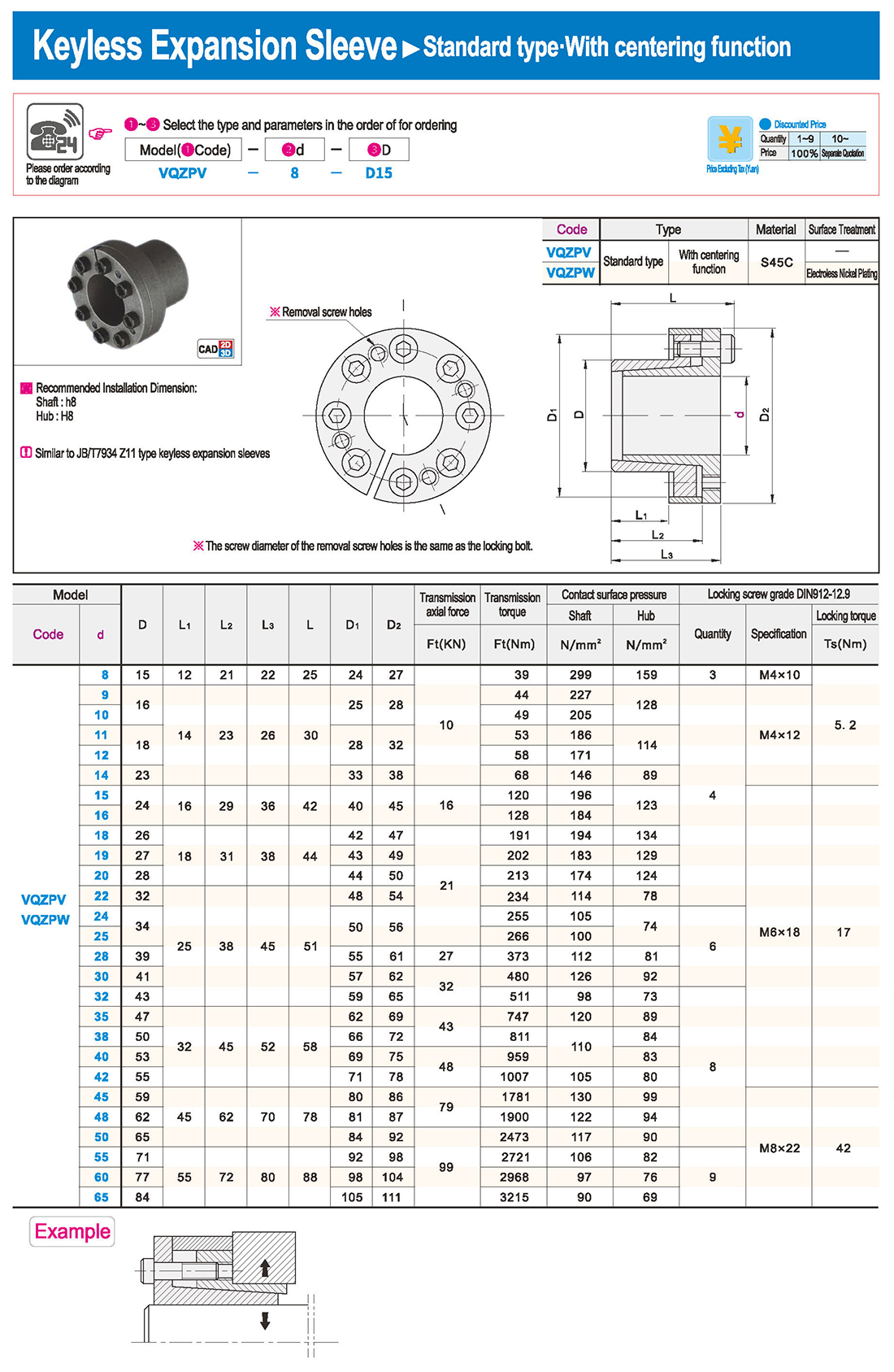
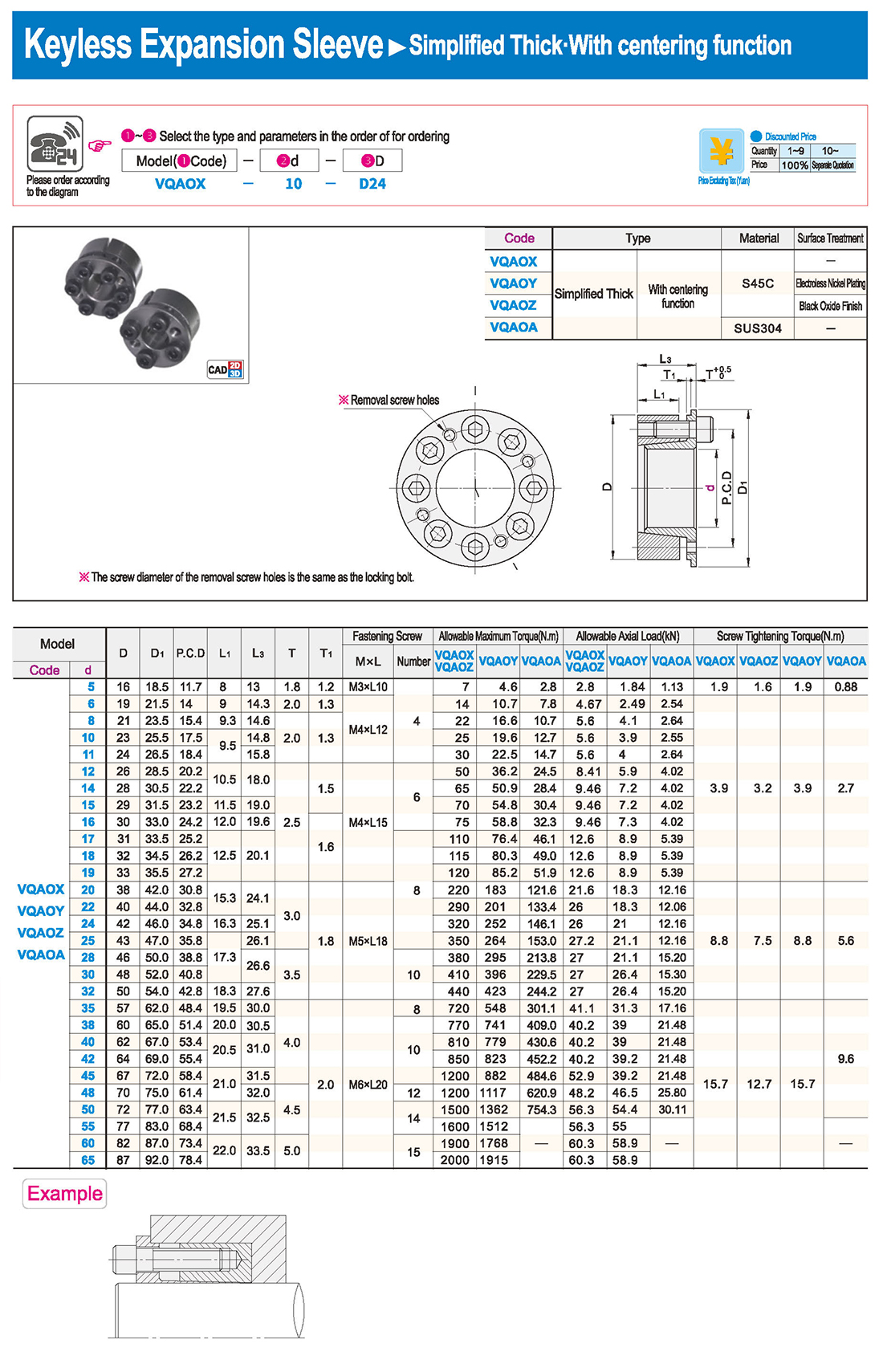
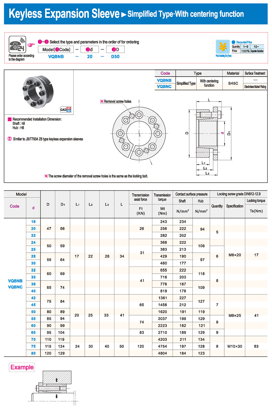
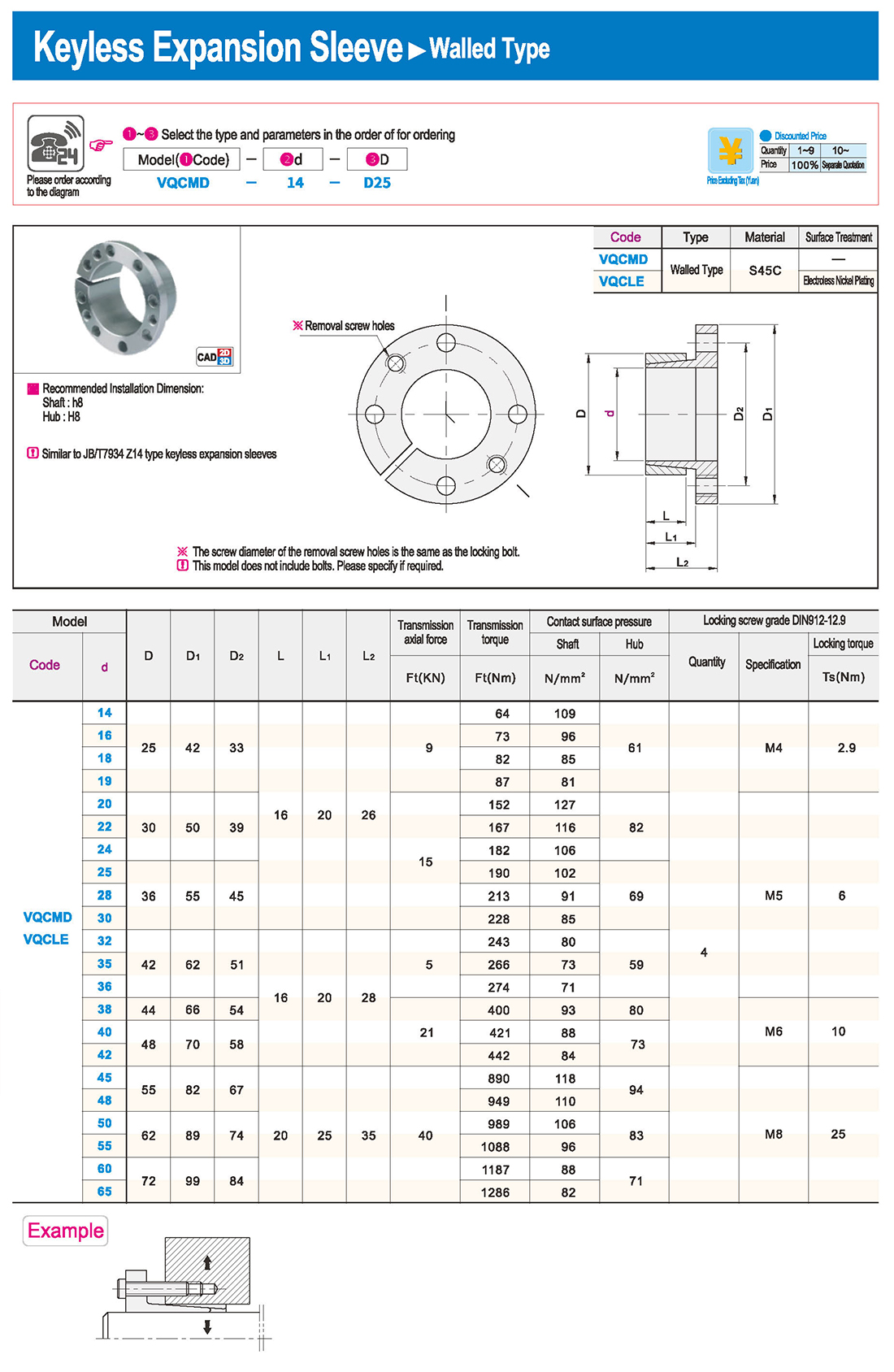
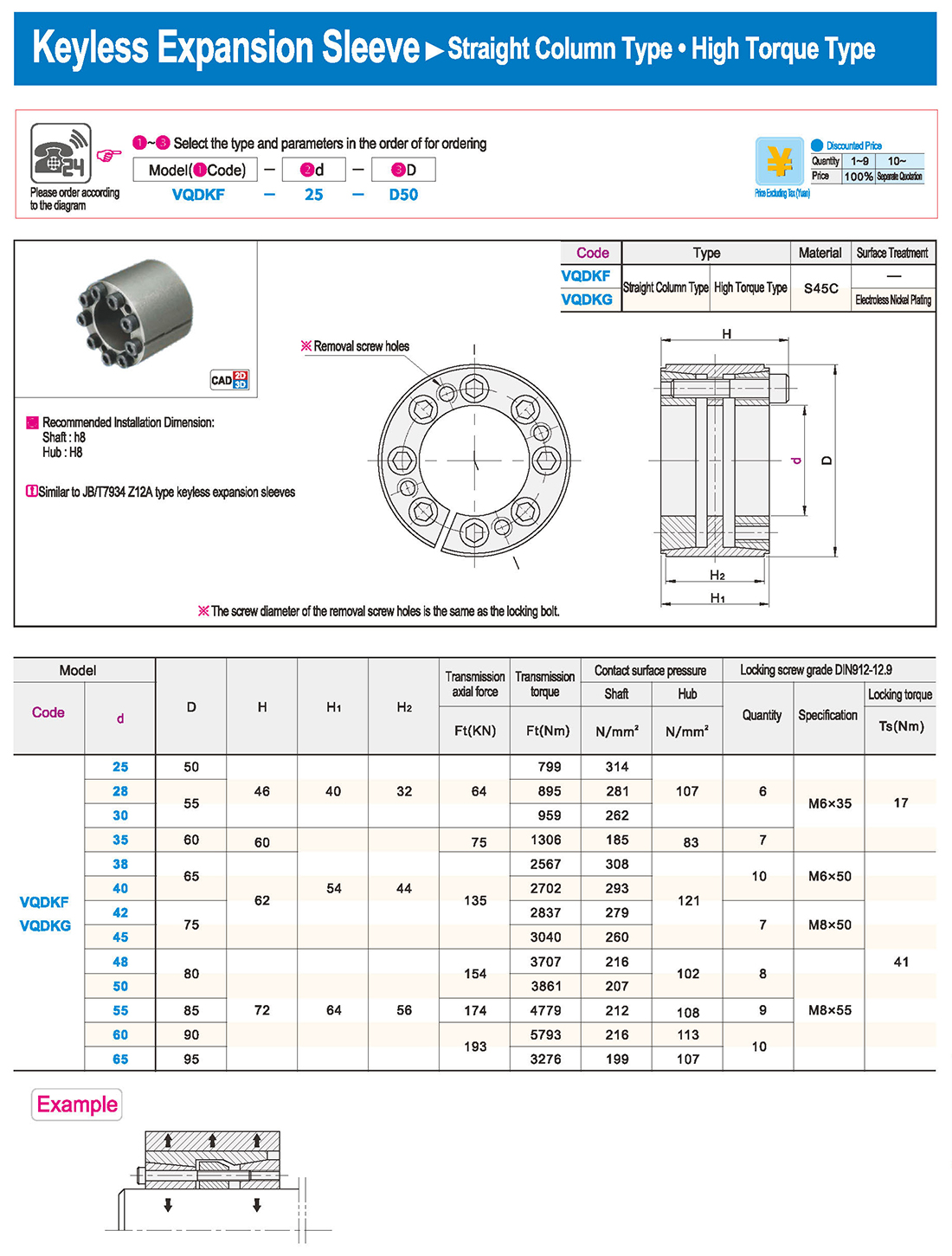
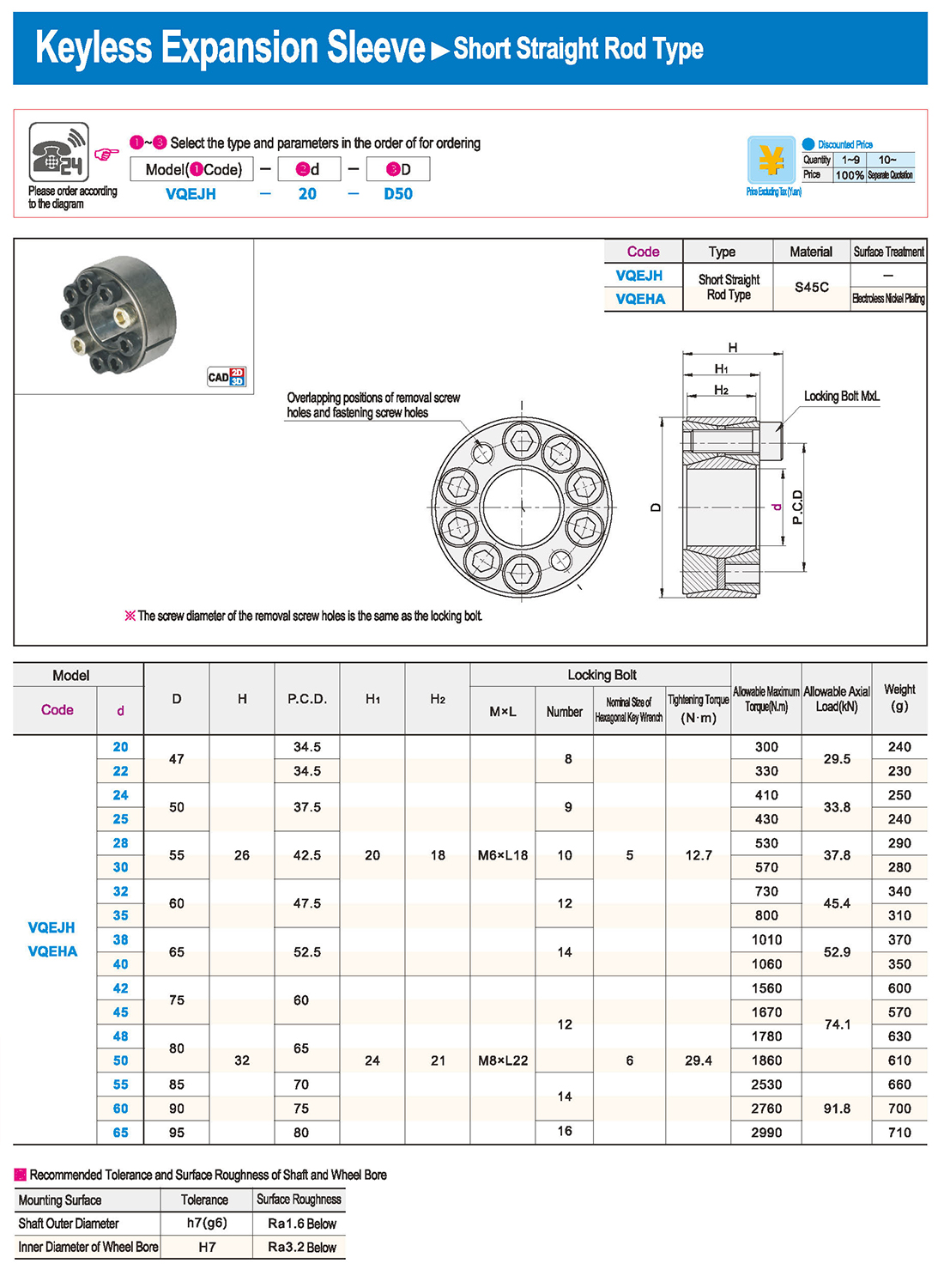
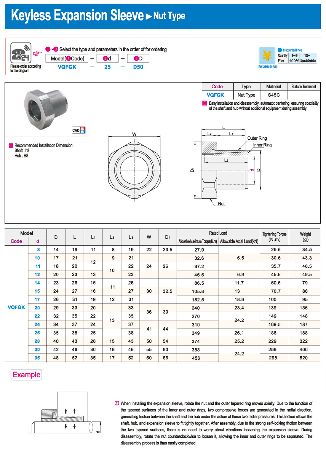
① The expansion sleeve connection involves placing a tensioning sleeve with mating inner and outer conical surfaces between the shaft and the hub. Under the pre-tightening force of high-strength bolts, the inner ring contracts and the outer ring expands, closely fitting the inner ring to the shaft and the outer ring to the hub, generating sufficient friction to transmit torque, axial force, or a combination of both.
② The expansion sleeve connection principle is simple and reliable, with convenient processing, installation, and disassembly operations that are easy to learn. It has been widely used in various machinery, proven to be a reliable and effective connection method.
Installation Steps
① Clean the protruding end of the main shaft and the inner hole of the expansion sleeve using fine gauze and cotton yarn. Check the dimensions of each part, and once confirmed, clean with gasoline or carbon tetrachloride. After cleaning, apply a thin layer of lubricating oil evenly on the surface of the main shaft, the contact surface of the expansion sleeve, the thread surface of the screw, and the support surface. (The lubricating oil must not contain molybdenum disulfide.)
② During assembly, loosen the screws and align the inner side of the expansion sleeve with the main shaft. Install it slowly and securely, ensuring to maintain a gap between the expansion sleeve and the main shaft throughout the installation process.
③ After positioning, tighten the screws manually, then use a torque wrench to tighten them uniformly in different diagonal and cross patterns.
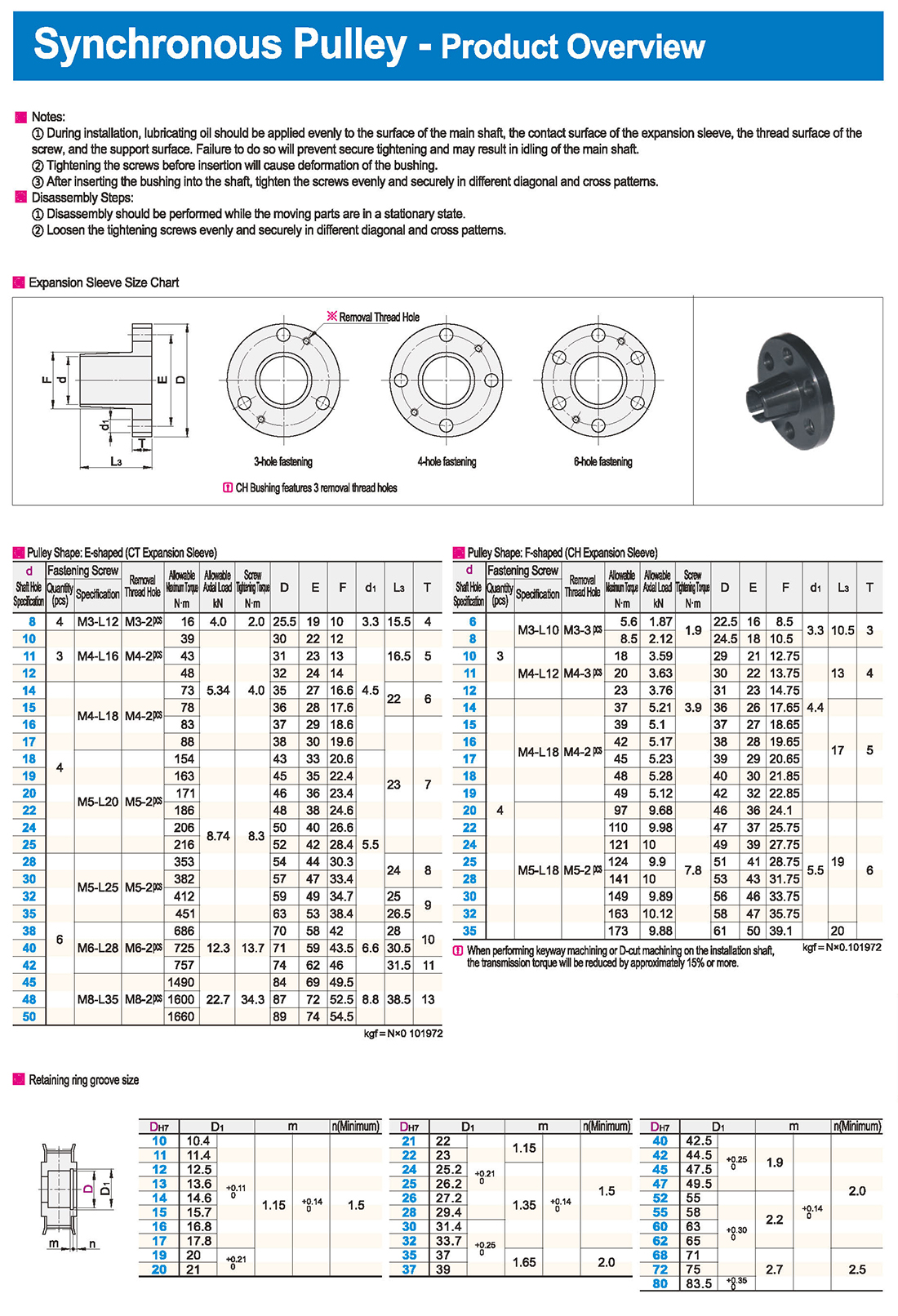
Notes:
① During installation, lubricating oil should be applied evenly to the surface of the main shaft, the contact surface of the expansion sleeve, the thread surface of the screw, and the support surface. Failure to do so will prevent secure tightening and may result in idling of the main shaft.
② Tightening the screws before insertion will cause deformation of the bushing.
③ After inserting the bushing into the shaft, tighten the screws evenly and securely in different diagonal and cross patterns.
Disassembly Steps:
① Disassembly should be performed while the moving parts are in a stationary state.
② Loosen the tightening screws evenly and securely in different diagonal and cross patterns.
 inglés
 ruso
ruso español
 italiano
 árabe
árabe coreano
 alemán
 Japonés japonés
 vietnamita
 turco
turco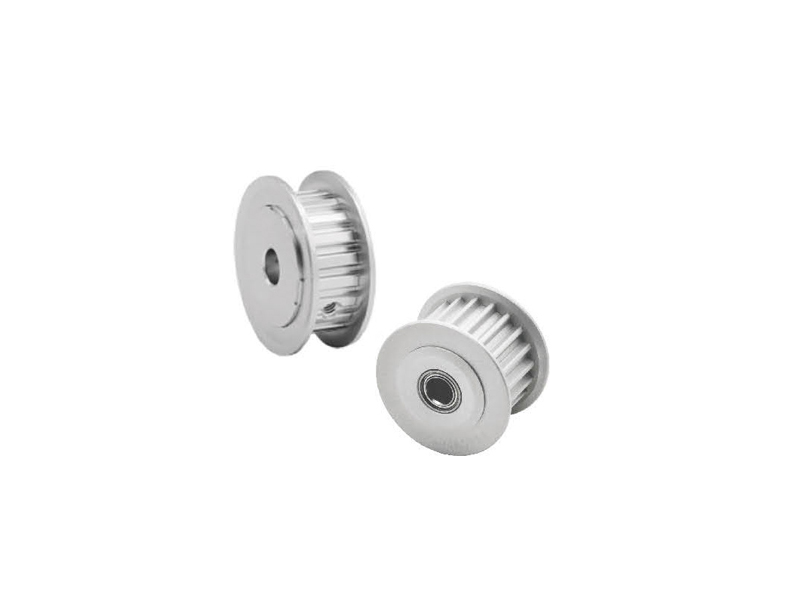


 introducción
 Tabla de especificaciones
 descargar
